How to remove the rear fascia of a DeLorean DMC 12
Here is a visual guide explaining how to remove the the rear fascia off a DeLorean DMC 12. It is easier to remove than the front fascia, but since there are a lot of bolts and nuts in the area, it’s good to know which are needed to be removed and which aren’t. This procedure removes the complete fascia still attached to the fiberglass support and the wire harness still connected. You can then further disassemble the fascia, once it is off the car.
This procedure is also covered in the Delorean Workshop Manual section P:02:19
Basically, the steps are: First
– Remove side markers and disconnect the bulbs from the holders
– Remove coil cover and disconnect black bulkhead connector
– Remove engine cover latch plate and disconnect latch cable
– Remove the tail lights Then
– Remove two 13 mm M8 bolts and two 10 mm M6 bolts behind each tail light
– There may also be a self tapering screw behind the tail light on the driver side
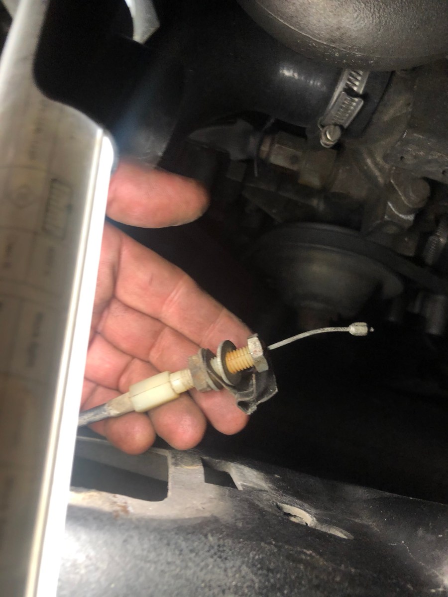
– Remove eight (or nine) 10 mm M6 nuts from the studs moulded into the fascia, going through the muffler heat shield and brackets (two vertical studs on the outside of the exhaust pipes and six horizontal studs distributed between the tail pipes)
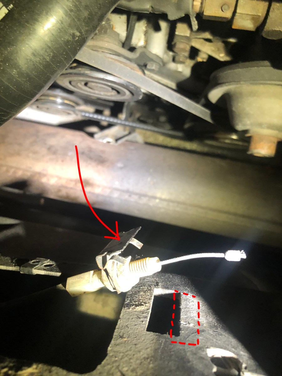
Lift out and away!
Do not remove those top 9 screws securing the fascia to the fiber glass support, there is no point unless you want to separate the fascia itself from the fiberglass support piece. Either way, always take the support piece and fascia off together, then separate the two after they’re out of the car.
Part one; remove wires and cables connecting the fascia to the rest of the car
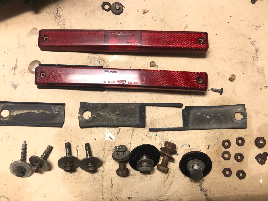
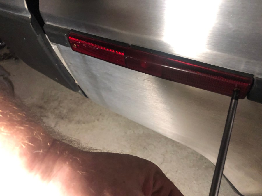
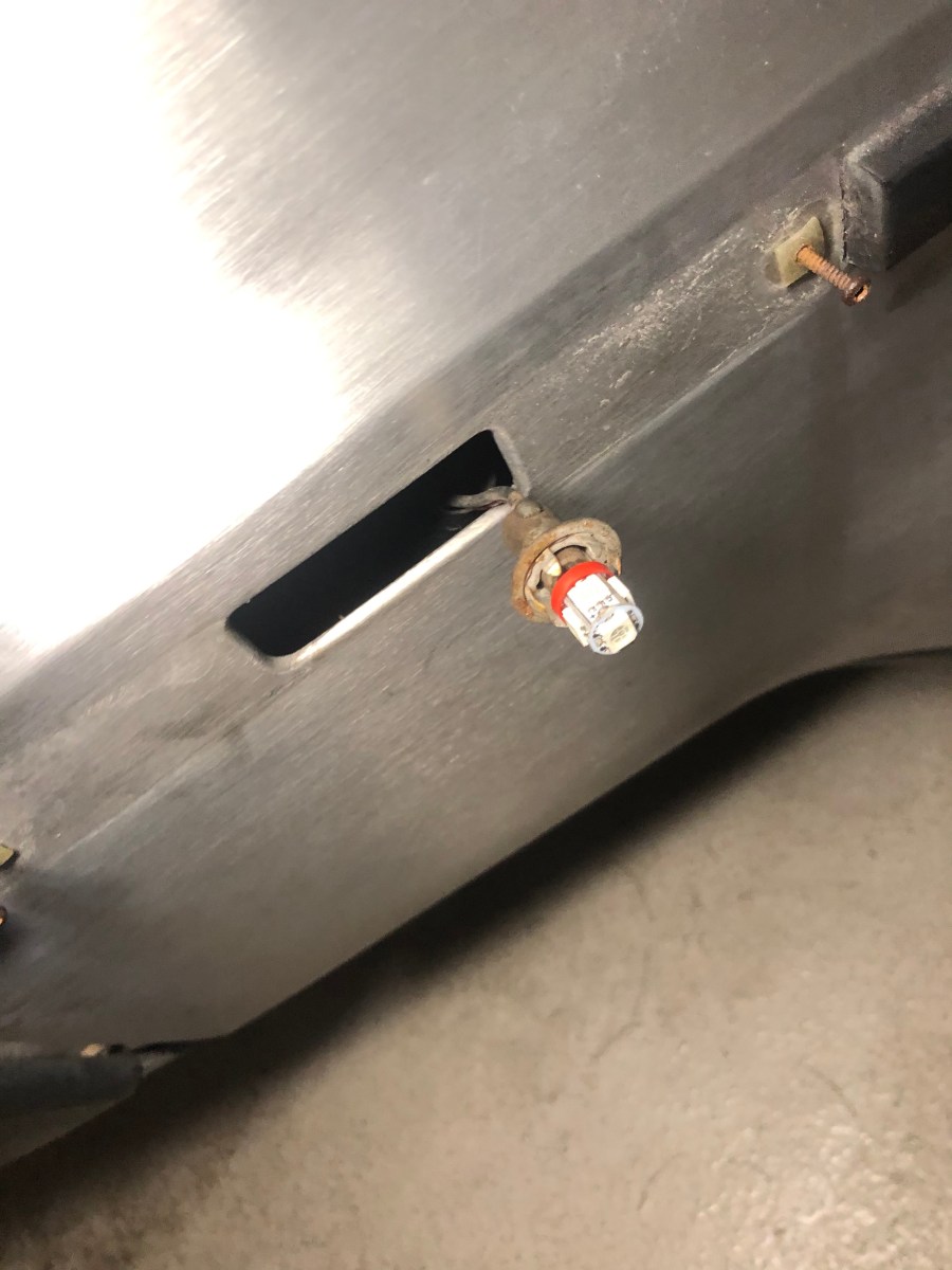
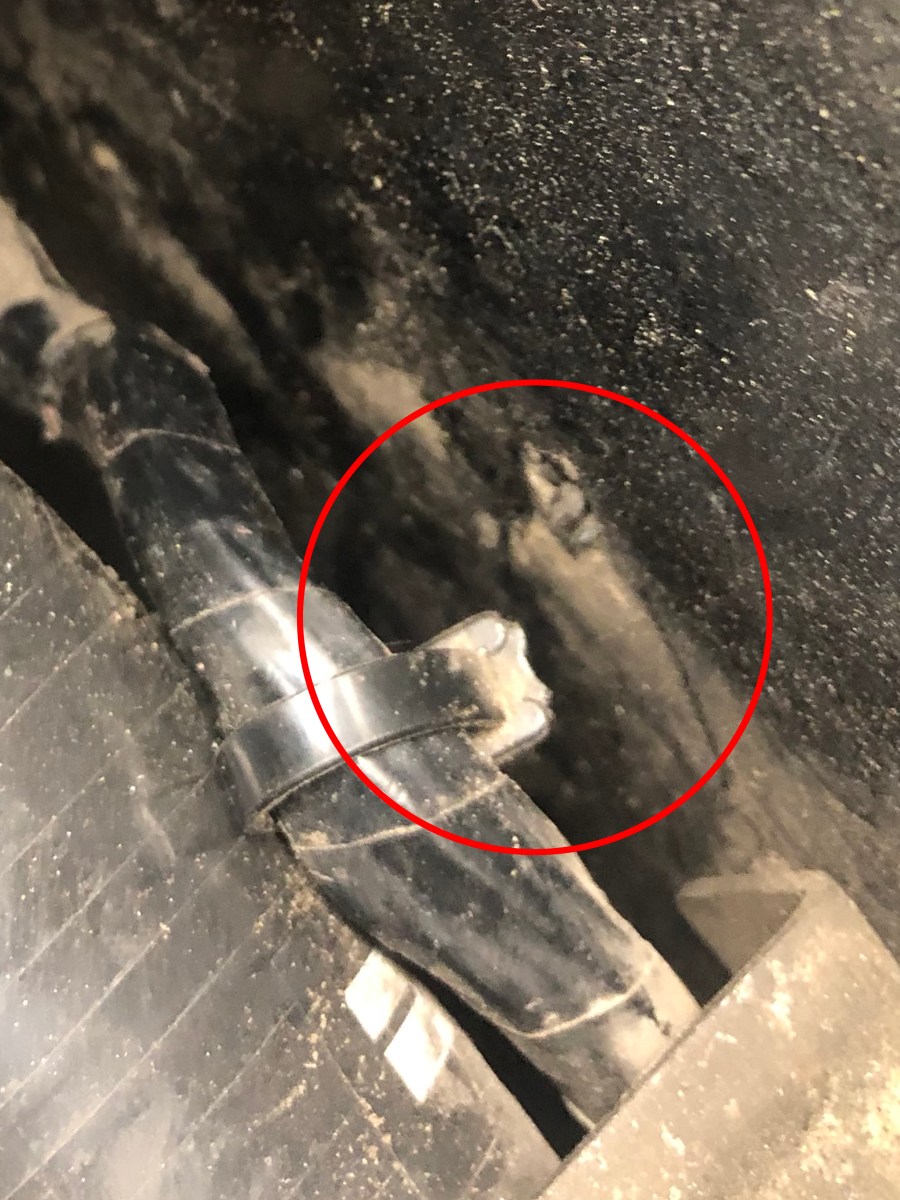
These are actually all the nuts and bolts required to be removed to be able to pull the rear fascia off the car. Not too bad.1. Start by loosening the rear side marker lights to be able to pop the bulb and wire out of its holder. All that is required is a small Philips screw driver.2. Once the lens is loosened, you pull on the bulb to get it out of the socket. I screwed the small self tapering screws back into their plastic nuts to not loose them. If you need to replace the plastic nuts, the bulb sockets or the gaskets, they are available from Deloreango.com and others.3. With the bulb now hanging free, just pop it back into the hole in the stainless panel. The wires connect to the fascia harness and are easily pulled out once the fascia is loose. You need to do this for both sides.4. To be able to pull the harness with all the tail and side light wires away together with the facia, all you need to do is to loosen the black connector in the bulkhead. Remove the plastic cover in the from passenger side corner of the engine bay covering the ignition coil to get to it. The connectors are held on by two tabs on the male side (the side that pulls out) which you press together with your thumb and index finger and then pull straight out. A good time to clean all contacts, I usually use a Dremel with a small brass wire brush.5. The wire loom is fed from the bulkhead along the passenger side fiberglass body and under the overflow bottle. It is attached in two places by cable ties with tiny push-in clips on them. The clips are pressed through small holes in the body. This and the next picture shows how one broke when I pulled it out.6. This is the broken cable tie which attached the wire loom to the body. The clip is still inside the little hole.7. On the second clip I used a small flathead screwdriver to press down on one of the tabs, so I could pull it out without damaging it. The clip is the little arrow-head looking plastic piece on the cable tie attached to the loom. It is pointing straight at the tiny hole where it was attached.8. Next, you need to loosen the cable which unlocks the engine cover. The latch cover is on the inside of the body, behind the license plate. It is held by two small Philips screws, and I also had to pry the cover loose due to some gasket material which had stuck fairly tight to the fiberglass. You can see the two small screws holding the cover in place circled in red.9. Here you can see the cover opened, and the cable runs behind it and is attached to its lever just to the left of the nuts in the picture. The odd metal frame hanging behind the cable is supposed to hold one of the license plate lights attached, but someone put speed nuts to hold mine instead.10. By tilting the cable in the lever you can easily pull the cable-stop out of its groove (inside the fascia). I found it easer to first completely remove the tin clip which holds the cable tensioner to the body. The clip is the black, bent metal part hanging on top of my middle finger. You then need to undo the end nut (the rightmost one in this picture) to take the clip off, to be able to pull the cable through the fascia later.11. Here you can see that you have to remove the rightmost nut from the cable tensioner to be able to remove the clip. I put the clip back where the red dashed box indicates. Then I put the nut back on the tensioner to not loose it. After that you can pull the cable out of the fascia.12. The red line in this image shows how the cable runs inside the fascia and out through a grommet in the rear driver side corner of the engine bay. The grommet is easily loosened, and then you can pull the cable and tensioner through.13. Here I have pulled the cable and the tensioner out through the hole in the fascia, and then I just placed it on top of the engine. Remember to keep track of it if you intend to start your engine, it can easily get stuck in the belts!
Part two: Now the wires and cables are loosened, we can focus on the nuts and bolts actually attaching the fascia.
14. Now that all wires and cables that connect the fascia to the rest of the car are loosened, we can start to loosen the actual fascia. The following description aplies to both driver and passenger side, except for the extra screw on the drivers side, mentioned below. A) To be able to access the bolts needed to be removed, you need to pop the rear lights out. They are held in by six Philips screws each. You technically don’t need to disconnect the lights from the harness, but it is probably a lot easier if you do. If the rear lights haven’t been rewired, it is simply a plastic connector attached to the PDB light bulb board. In the image you can see which four nuts are needed to be removed circled in red. B) There are two 13 mm M8 bolts behind each tail light, that run though the fascia and in to an L-shaped bracket bolted to the fiberglas body. You can see the two holes to the right in this picture where the bolts used to sit. I used a long 13 mm socket and a ratchet extension on the bolt on the outside, and held the nut with a 13 mm wrench on the inside. C) Next, behind each tail light, there are also the two 10 mm M6 bolts that screw directly in to inserts in the fiberglass body on the other side of the fascia, so you can not see the backside of them in the engine bay. Just undo the 10 mm bolts and remove them together with any washers. D) Do the same on both sides. E) Then, on the driver side only, there may be a 5th screw that need to be removed. It is just above the top 10 mm M6 bolt in the picture, also circled in red. I don’t know exactly what it does, it is a self tapering screw that also goes in to the fiber glass body.15. Here are the holes in the L-shaped bracket on the rear inside of the engine bay (driver side) where the bolts came through and where the 13 mm nuts were attached. Technically, you could probably just as well loosen the other two bolts in the L-bracket, the ones that goes into the fiberglass body, instead, but I choose to leave the bracket on the car, and therefore loosening the two bolts that run from rear towards the front.16. Here are the same holes on the inside of the engine bay but on the passenger side. The 13 mm M8 bolts came through here and were held on by two 13 mm nuts. You can also see the black wire loom wrapped in electrical tape, that will be removed with the fascia, after you have disconnected the black connector from the bulkhead behind the coil cover. The whole loom will be removed with the fascia, there is no need to loosen the rubber grommet you see in bottom right of the picture.17. When the bolts behind the tail lights are removed, you need to get under the car. This picture is taken underneath the car facing up. The big rusty part on the right is the muffler and also shown at the bottom of the image is the driver side tail pipe. Circled in red are three of the M6 studs that hold the fascia to the muffler bracket, and in this pic the 8 mm nuts have already been removed and the studs then pulled backwards a few cm through the metal sheet you see in front of them. I also used a flathead screwdriver to pry the fascia from the bracket. There are in total eight such studs moulded in to the fascia plastic, six of them run parallell to the ground (three visible here), and through the muffler bracket. There are also one more on each side that goes vertical, roughly where the arrow is pointing, on the outside of the tail pipes. These all snap quite easy, and if they do, you need to get new ones (stainless are available) and epoxy them in to the fascia. Only the two outer ones snapped on me, luckily. When I removed the front fascia, almost all of them snapped. Note: in the workshop manual there are seven horizontal studs, I only counted six.18. This just shows me having to cut the wire to my third brake light which connect to the brake light in the passenger side rear light PDB board. I had made the third brake light removable by installing a connector at the top of the louvre, should I have to remove it, but I didn’t plan for removing the rear fascia. I will install a 2-pin connector down here as well when I assemble everything.19. When all bolts are removed, you can pull the fascia straight out (backwards) and lift if off the car. Make sure you have separated the studs att the bottom of the fascia from the muffler bracket. You will have the complete wire loom still attached, with the wires for the rear lights, the side marker lights and the black connector for the bulkhead.20. Here is an image showing the engine bay without the fascia, and I have marked where the bolts attach. On top of the engine is the cable for the engine cover latch.